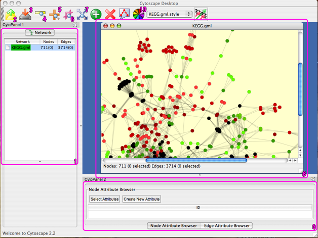
The Cytoscape window should look something like the picture above (there may be some minor differences related to the OS you are using). The pink squares and numbers show some functions that you may find useful. Here is a very brief description of them. If you want to have a longer description and/or a description of other Cytoscape functions, you should refer to Cytoscape help.
-
1. Network Section : It is here that you chose the network that you are viewing.
-
2. Load : Used to load a file
-
3. Save : Used to save a file
-
4. Zoom Out : Zoom out in the Network View
-
5. Zoom In : Zoom in in the Network View
-
6. Zoom Selected Region : Adapt the Network View zoom to the selected gene(s)
-
7. View All : Adapt the Network View to see all genes
-
8. Network View : A view of the network with all the colored genes. It is here that you can select one or multiple genes.
-
9. Attribute Browser : Name and attributes of the selected genes/edges
-
10. Set Visual Style : Define the color of the nodes
Quick start with Cytoscape

-
•The first thing to do is to load the Network file. Use the appropriate button (1) and load the KEGG.gml file.
-
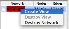
•The file we use is a little bit big so we have to create a view. Right-click on the KEGG.gml object in the Network Section and select Create View. Now you can explore the network with Cytoscape but we still have to define a visual style.
-
•To define a visual style, we have to load the different separator values. Select File>Load>Expression Matrix File... and load the KernelChipEigenValueFiltering.mrna file.
-
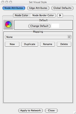
•Left-click the Set Visual Style button (10) and create a new style then define it.
-
•You can then define a Visual Style scheme for the network. The following example works with the Node Color attribute, but it works the same way with other attributes (like Node Border Color, Node Shape, etc)
-
•First, you have to select the attribute you want to create a color scheme for. Left-click Node Attributes and Node Color. Then you have to create a New mapping. Left-click New.
-
•A new window opens, asking you to choose a mapper. Choose Continuous Mapper and define its name.
-
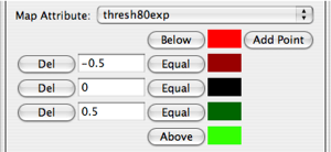
•You then have to select the corresponding map attribute. ThresholdXexp corresponds to the separator with X% of the eigenvalues removed. For example, to obtain the pictures of the paper, we chose to remove 80% of the eigenvalues, so that we chose the Threshold80exp attribute.
-
•Then you have to chosse a scale of colors. Each time you had a point (with the Add Point button), you had a color and a level in the scale. The first color (the upper one) corresponds to the lowest values and the last (lower) one to the highest values. The values of the stages are the values written on the left.
-
•Left-click on Apply to Network to color the network accordingly to this scale.
-
•You can of course change multiple attributes of the network at the same time.


